
Common Questions About USB Data Cables: Answers & Solutions
2025-03-07
MFi Certified: Everything You Need to Know
2025-03-07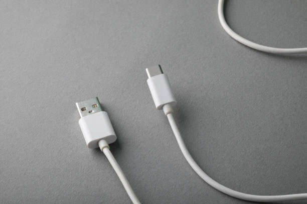
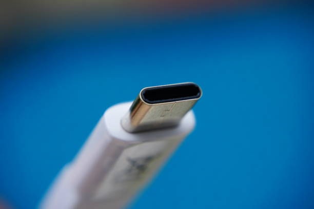
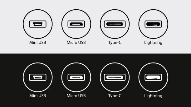
The USB Type-C connector, also known as USB-C, has become the standard for many electronic devices due to its versatility and user-friendly design. This modern connector supports fast data transfer, high-resolution video, and rapid power delivery, making it an essential feature for modern technology. Its widespread adoption across smartphones, laptops, gaming consoles, and other electronic peripheral devices, speaks volumes about its utility. In this blog, we’ll dive deep into the intricacies of the USB Type-C pin layout, explaining its components and functionality while exploring its advantages over previous USB types.
Contents
- 1 What Is USB-C?
- 2 USB-C or USB Type-C?
- 3 Features of USB-C
- 4 Overview of USB Type-C
- 5 Comparison of USB 2.0 and USB 3.x Series Modules
- 6 Anatomy of the USB Type-C Connector
- 7 Pin Categories in USB-C
- 8 USB Type-C Pin Layout Diagram
- 9 Functional Roles of the USB-C Pins
- 10 Advantages of USB Type-C Pin Layout
- 11 Differences Between USB-C Male and Female Pinouts
- 12 Conclusione
What Is USB-C?

USB-C is a modern connectivity standard that supports high-speed data transfer rates of up to 10Gbps and power delivery capabilities of up to 100W. These features make USB-C a versatile and universal standard for contemporary devices.
USB-C or USB Type-C?
The terms “USB-C” and “USB Type-C” are used interchangeably (both will be used throughout this explanation). However, “USB Type-C” is the official designation as listed by USB.org.
Features of USB-C
USB-C offers three key features:
- Reversible Connector: The plug can be inserted in any orientation relative to the receptacle, eliminating the need to determine the “correct” way to plug it in.
- Broad Protocol Support: It supports USB 2.0, USB 3.0, and USB 3.1 Gen 2 standards, along with third-party protocols like DisplayPort and HDMI through a mode called Alternate Mode.
- Power Negotiation: Devices can communicate to negotiate the appropriate level of power delivery through the interface.
The following sections detail how the USB Type-C standard implements these features.
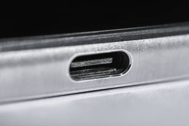
Overview of USB Type-C

USB Type-C is a reversible connector, meaning there is no “wrong way” to plug it in. This feature alone has simplified the user experience significantly and eliminated the frustrations associated with earlier USB designs. With 24 pins in total, the USB-C connector is designed to handle a variety of signals and power requirements, from charging small devices to supporting high-bandwidth applications like 4K video transmission and high-speed external drives.
Before we delve into the specifics of the pin layout, let’s highlight some key features of USB-C:
- Reversible design: No more fumbling to insert the connector correctly, as it works seamlessly regardless of orientation.
- Higher power delivery: USB-C supports up to 240W of power delivery with the USB Power Delivery (USB PD) standard, making it suitable for even high-powered devices.
- Enhanced data transfer speeds: USB-C supports data transfer rates up to 40Gbps with the USB4 protocol, catering to demanding applications like 8K video streaming and virtual reality.
- Versatile functionality: It can support multiple protocols like DisplayPort, HDMI, and Thunderbolt through alternate modes, reducing the need for multiple cables.
- Compact size: Despite its capabilities, USB-C maintains a slim and compact form factor, making it ideal for modern, lightweight devices.
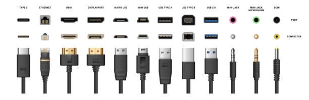
Comparison of USB 2.0 and USB 3.x Series Modules
Key Differences
- USB 2.0: Simpler pinout and differential pair topology. Requires adapters for USB-C due to pin and receptacle differences. Can face power issues from mismatched pull-up resistors. Offers longer cable lengths.
- USB 3.x: Introduced with USB-C and supports high-speed differential pairs, allowing significantly faster data transfer rates. USB 3.x standards support higher current output and may use USB 2.0 differential pairs as backups.
USB 2.0 Pinout Table (Using USB-C)
| Bus Power | A4 | VBUS | B9 | VBUS |
| A5 | B8 | |||
| USB 2.0 Data (+) | A6 | D1+ | B7 | D2- |
| USB 2.0 Data (-) | A7 | D1- | B6 | D2+ |
| A8 | B5 | |||
| Bus Power | A9 | VBUS | B4 | VBUS |
| A10 | B3 | |||
| A11 | B2 | |||
| Ground | A12 | GND | B1 | GND |
USB 3.x Pinout Table (Using USB-C)
| Pin Description | Pin A | Pin Name | Pin B | Pin Name |
| Ground | A1 | GND | B12 | GND |
| SuperSpeed TX Pair (Positive) | A2 | TX1+ | B11 | RX1+ |
| SuperSpeed TX Pair (Negative) | A3 | TX1- | B10 | RX1- |
| Bus Power | A4 | VBUS | B9 | VBUS |
| Configuration Channel (CC) | A5 | CC1 | B8 | CC2 |
| A6 | B7 | |||
| A7 | B6 | |||
| A8 | B5 | |||
| Bus Power | A9 | VBUS | B4 | VBUS |
| SuperSpeed RX Pair (Negative) | A10 | RX2- | B3 | TX2- |
| SuperSpeed RX Pair (Positive) | A11 | RX2+ | B2 | TX2+ |
| Ground | A12 | GND | B1 | GND |
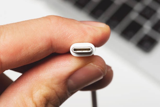
USB Type-C Connector and Pin Layout
The USB Type-C connector features 24 pins. Below are descriptions of key pin groups:
USB 2.0 Differential Pairs
- The D+ and D- pins form differential pairs for USB 2.0 data transmission.
- Two sets of D+ and D- pins exist for redundancy, ensuring functionality regardless of connector orientation. In practice, only one USB 2.0 differential pair is utilized.
| Feature | USB 2.0 | USB 3.x |
| Data Transfer Speed | Up to 480 Mbps | Up to 10 Gbps or higher |
| Power Output | Up to 2.5W | Supports higher power levels |
| Cable Length | Longer cables possible | Limited due to high speeds |
| Backward Compatibility | Sì | Sì |
| High-Speed Differential Pairs | Not used | Fully utilized |
| Introduced with USB-C | No | Sì |
Choose the module based on device compatibility maximum power and performance needs.
Power and Ground Pins
- VBUS and GND pins handle power supply and grounding.
- The default VBUS voltage is 5V, but devices can negotiate higher voltages through USB Power Delivery (PD), allowing up to 20V and 5A, for a total power output of 100W.
- This adaptability enables USB-C to power a variety of devices, from smartphones to notebook computers, using a single cable.
RX and TX Pins
- Two RX differential pairs and two TX differential pairs are present.
- These pairs enable USB 3.0/3.1 connectivity. A multiplexer ensures proper routing of data through the cable when the connector is flipped.
- In some implementations, the RX and TX pairs can be used for additional USB Type-C functionalities, such as Alternate Mode or USB PD, when USB 3.0/3.1 is not in use.
CC1 and CC2 Pins
- The Channel Configuration (CC) pins support several functions, including:
- Detecting cable attachment and removal.
- Determining plug orientation.
- Advertising current capabilities.
- Enabling communication for USB PD and Alternate Mode.
By monitoring the voltage levels on the CC pins, devices can infer connection orientation and available current. For instance:
- ~0.41V corresponds to default USB power (500mA for USB 2.0, 900mA for USB 3.0).
- ~0.92V indicates a source current capability of 1.5A.
- ~1.68V indicates a source current capability of 3A.
VCONN Pin
- The VCONN pin supplies 5V/1W power to active components in the cable, such as electronically marked chips or re-drivers, which are used to strengthen signals over longer cable runs.
SBU1 and SBU2 Pins
- These pins handle low-speed signals used exclusively in Alternate Mode.
USB Power Delivery (USB PD)
USB PD enables devices to negotiate the required power levels over the CC line. This single-wire communication protocol allows:
- Dynamic adjustment of VBUS voltage (e.g., from 5V to 20V) based on device requests.
- Flexible power delivery, enabling efficient charging of diverse devices.
For example:
- A sink device (e.g., a laptop) requests a 9V bus voltage.
- The source (e.g., a charger) stabilizes the voltage and sends a “power-supply-ready” signal.
- Later, the sink may request a 5V bus voltage, and the source adjusts accordingly.
Additionally, USB PD facilitates other negotiations, such as those related to Alternate Mode functionality.
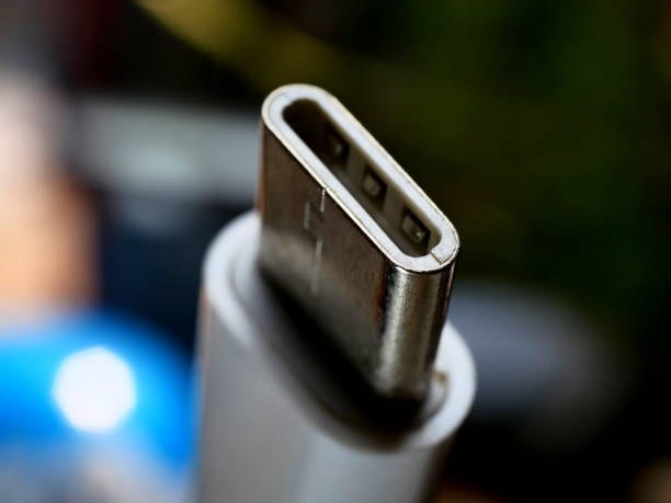
Anatomy of the USB Type-C Connector
The USB-C connector consists of 24 pins arranged in a symmetrical layout, which enables its reversible nature. These pins are grouped into different categories based on their functions, such as power delivery, data transfer, and configuration usb type c cable. The design of the connector specification the pin layout ensures efficiency, reliability, and compatibility with a wide range of devices and applications.
Pin Categories in USB-C
- Vbus Pins (Power Supply):
- USB-C has four Vbus pins (pins A4, A9, B4, B9) that supply power to connected devices. These pins play a critical role in delivering varying levels of power, ranging from 5V to 20V, depending on the USB PD specification. With the latest enhancements, USB-C can deliver power levels up to 48V at 5A, supporting high-powered devices like laptops and monitors.
- Ground Pins:
- The connector includes four ground pins (pins A1, A12, B1, B12) to ensure a stable electrical connection. These pins provide a return path for electrical current and enhance safety and stability.
- TX/RX Pairs (SuperSpeed Data Lines):
- USB-C features four differential pairs for high-speed data transmission. Two pairs (A2, A3 and B10, B11) handle USB 3.x SuperSpeed data in one direction (TX), while another two pairs (B2, B3 and A10, A11) handle data in the opposite direction (RX). These pins enable impressive data transfer rates and ensure seamless functionality for applications requiring high bandwidth.
- Configuration Channel (CC) Pins:
- The CC pins (A5 and B5) are essential for determining the orientation of the cable, negotiating power delivery, and supporting alternate modes like DisplayPort. These pins also facilitate device detection, ensuring proper communication between connected devices.
- Sideband Use (SBU) Pins:
- SBU1 (A8) and SBU2 (B8) are used for low-speed signaling in alternate modes, such as audio adapters or video transmission. These pins enhance the versatility of USB-C by enabling additional functionalities.
- D+/D- (USB 2.0 Data Lines):
- These pins (A6, A7 and B6, B7) provide backward compatibility with USB 2.0, supporting legacy devices and lower-speed data transfers. This ensures a seamless transition to USB-C for users with older peripherals.
USB Type-C Pin Layout Diagram
A simplified representation of the USB-C pin layout looks like this:
Top Row (Pin Group A):
- A1: Ground
- A2, A3: TX1+
- A4: Vbus
- A5: CC1
- A6, A7: D+
- A8: SBU1
- A9: Vbus
- A10, A11: RX1+
- A12: Ground
Bottom Row (Pin Group B):
- B1: Ground
- B2, B3: TX2+
- B4: Vbus
- B5: CC2
- B6, B7: D-
- B8: SBU2
- B9: Vbus
- B10, B11: RX2+
- B12: Ground
Functional Roles of the USB-C Pins
Power Delivery
One of the standout features of USB-C is its advanced power delivery capabilities. The Vbus pins can deliver up to 240W of power using USB PD 3.1, making it suitable for charging laptops, monitors, and even small appliances usb c cable. The CC pins play a crucial role in negotiating power levels and ensuring compatibility between devices. This adaptability in power delivery technology makes USB-C a practical choice for everything from smartphones to high-performance gaming laptops.
Data Transfer
With support for USB 3.2 and USB4, the TX and RX pairs enable data transfer rates ranging from 5Gbps to 40Gbps. These pins ensure that users experience seamless data transfer for applications like external storage, video conferencing, and virtual reality setups custom usb cables. Additionally, the integration of Thunderbolt technology in some USB-C implementations allows for even faster data rates and extended functionalities, including daisy-chaining data wires between multiple devices.
Alternate Modes
The CC and SBU pins facilitate alternate modes, allowing USB-C connectors to transmit video signals using protocols like DisplayPort, HDMI, or Thunderbolt. This feature makes USB-C a one-cable solution for many devices, simplifying connectivity for users. With alternate modes, USB-C can support up to dual 4K displays or even an 8K monitor, demonstrating its immense potential for multimedia applications downstream facing port. Alternate Mode allows USB Type-C to support third-party protocols like DisplayPort or HDMI. While implementing an Alternate Mode, a connection must still support USB 2.0 and USB PD, ensuring backward compatibility and efficient power delivery.
Legacy Compatibility
USB-C’s inclusion of D+/D- pins ensures that it remains compatible with older USB 2.0 devices. This backward compatibility allows for a smooth transition to the newer standard without rendering older devices obsolete. The ability to connect legacy devices without additional adapters or converters underscores USB-C’s versatility and user-friendliness.
Advantages of USB Type-C Pin Layout

- Reversibility: The symmetrical pin layout enables easy, error-free connections, reducing wear and tear on ports and cables.
- Future-Proofing: With support for evolving protocols like USB4, the USB-C standard is built to adapt to future technological advancements, ensuring longevity and continued relevance.
- High Versatility: The combination of power delivery, data transfer, and video output in a single connector reduces cable clutter and enhances usability. This versatility is particularly beneficial in professional and multimedia environments.
- Enhanced Power and Speed: USB-C delivers more power and faster data rates than its predecessors, making it suitable for demanding applications such as video editing, gaming, and large-scale data transfers.
- Compact and Durable Design: Despite its robust capabilities, USB-C connectors are small and durable, ideal for the sleek designs of modern devices.
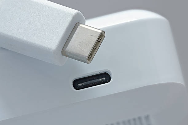
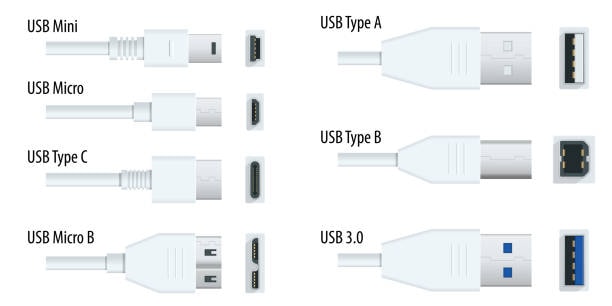
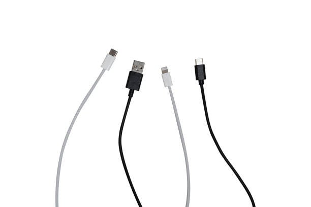
Differences Between USB-C Male and Female Pinouts

USB connectors, including USB-C, are available in male and female configurations to facilitate connections between devices. This differentiation ensures compatibility, as a connection always requires components with opposite genders, regardless of the USB type.
Additionally, various adapters c cables and converters are available with configurations like male-to-male, female-to-female, male-to-female, and female-to-male, enabling connections between different USB types and generations active cables usb implementers forum.
Female USB Connectors
A female USB connector is often referred to as a port, slot, receptacle, or socket. It is commonly integrated into host devices c cables or hubs and serves as the point where external USB peripherals are plugged in. Female USB-C connectors are typically embedded in the hardware casing of larger devices, such as laptops, monitors, or docking stations.
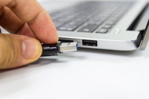
Male USB Connectors
A male USB connector, frequently called a plug, is found at the end of a cable or directly attached to smaller devices like USB flash drives. This plug is designed to fit into a female port, establishing a secure and functional connection. Male USB-C connectors are typically located on cables, accessories, or portable devices.
Key Characteristics
- Female Connectors: Provide the interface for external devices to connect; fixed in place on larger devices.
- Male Connectors: Designed for insertion into female connectors; often part of detachable or portable accessories.
These distinct roles ensure reliable and consistent connections in USB systems, including devices connected to the USB-C standard.
USB-C Pinout Table
| Descrizione | Signal A | Pin A | Pin B | Signal B | Descrizione |
| Ground | GND | A1 | B12 | GND | Ground |
| SuperSpeed differential pair 1 TX (+) | TX1+ | A2 | B11 | TX1+ | SuperSpeed differential pair 1 RX (+) |
| SuperSpeed differential pair 1 TX (-) | TX1- | A3 | B10 | TX1- | SuperSpeed differential pair 1 RX (-) |
| Bus Power | VBUS | A4 | B9 | VBUS | Bus Power |
| Configuration Channel | CC1 | A5 | B8 | SBU2 | Sideband use |
| USB 2.0 differential pair, position 1 (+) | D1+ | A6 | B7 | D2- | USB 2.0 differential pair, position 2 (-) |
| USB 2.0 differential pair, position 1 (-) | D1- | A7 | B6 | D2+ | USB 2.0 differential pair, position 2 (+) |
| Sideband use | SBU1 | A8 | B5 | CC2 | Configuration Channel |
| Bus Power | VBUS | A9 | B4 | VBUS | Bus Power |
| SuperSpeed differential pair 2 RX (-) | RX2- | A10 | B3 | TX2- | SuperSpeed differential pair 2 TX (-) |
| SuperSpeed differential pair 2 RX (+) | RX2+ | A11 | B2 | TX2+ | SuperSpeed differential pair 2 TX (+) |
| Ground | GND | A12 | B1 | GND | Ground |
Conclusione
The USB Type-C pin layout exemplifies the advancements in connector technology, offering unparalleled versatility, power delivery, and data transfer capabilities. By integrating multiple functionalities into a single, reversible connector, USB-C has set a new standard in the tech industry. Understanding the intricacies of its pin layout provides insight into why this connector has become a cornerstone of modern electronic devices. Its ability to adapt to new protocols and evolving power and data requirements ensures that USB-C will remain relevant for years to come.
Summary
The USB Type-C connector, with its 24-pin symmetrical design, combines power delivery, high-speed data transfer, and versatile functionality. From its Vbus and ground pins to its TX/RX pairs and configuration channels, each pin plays a vital role in supporting USB-C’s advanced features. This comprehensive understanding of the USB-C pin layout highlights its transformative impact on technology and its potential for future innovation. As USB-C continues to evolve, its role in shaping the future of connectivity cannot be overstated.


