
What USB Type Do I Have? A Comprehensive Guide to Identifying Your USB Ports
2025-03-08
iPhone Charger Wire Not Working: A Comprehensive Guide
2025-03-08
For the average person, a USB cable is simply a basic gadget used for transferring data or powering electronic devices. However, inside these seemingly mundane cables lies complex wiring that supports multiple operational functions. Understanding the number of wires inside a USB device or cable is essential for grasping how they operate. This article explores the details of USB wiring, examining various types of USB cables and their physical wire arrangements. If you’ve ever wondered how many wires in a USB cable, this guide will provide you with all the answers.
What is a USB Cable?
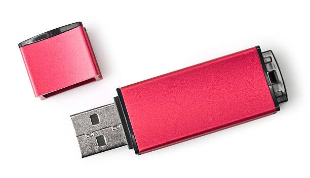
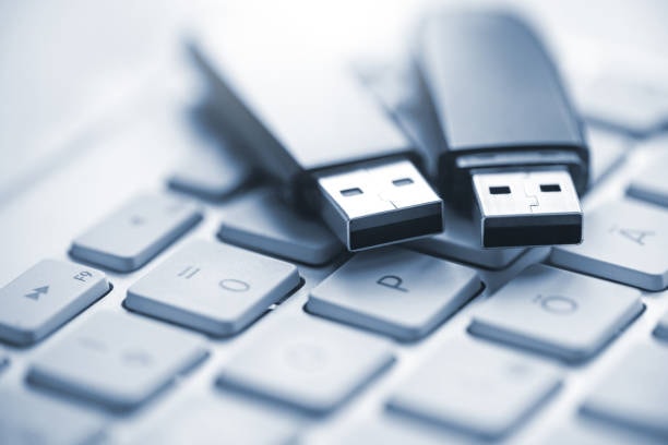
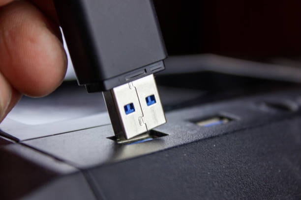
The Universal Serial Bus (USB) cable functions as a connector between various products for data communication while acting as a power channel for device charging and data movement. The evolution of USB cables moved from basic transmission tools to multiple-function cables which simultaneously move power and data quickly. Theusb cables function as connector devices between multiple electronic devices such as smartphones laptops printers external drives and numerous other devices.
Discovery of the standard USB cable shows these wires having defined assignments that help the utility of the cable. Different USB cable types employ various wire configurations and numbers corresponding wires which determine specific functionality limits that users need to understand.
Components of a USB Cable
Multiple carefully designed components within a USB cable unite to enable hassle-free power distribution nd data communication. Every USB cable model including both older Micro USB versions and modern USB-C versions employs an advanced internal design that prioritizes both durability and operational effectiveness. Below is a detailed breakdown of the key components of a USB cable:
1. Wires (Conductors)
USB cables consist of four fundamental elements named conductors which function to transport both electric power and data signals between connected devices. The functional elements of charging devices on the cable depend on these wires which guarantee the cable’s operations.
- Most USB cables contain four essential wire types which fulfill independent functions. The cable contains wires which transport data alongside wires delivering positive voltage and ground.
- Different advanced USB standards like USB 3.0 and USB-C add supplementary wires to deliver optimal power distribution together with more rapid data transmission.
- Laminations of premium copper components form these wires to enable both stable operation across extensive transmission lengths and highly efficient power delivery.
2. Inner Insulation
Each single wire maintains a coating of internal protection that protects the circuit. This protective coating serves multiple purposes:
- Electric short circuits are prevented because wiring isolation works to prevent direct wire contact.
- The wires each receive a distinct color on their inner insulation sheathing which identifies their assignments with red signifying VCC power and black for ground uses and green for Data+ and white for Data-.
- Polymers such as polyethylene function as inner insulation materials because they demonstrate good electrical insulation capacity with heat resistance and durability properties.
3. Shielding
A shielding layer beneath exterior cable insulation acts as an essential component to defend against electromagnetic interference (EMI). The reliability of data transport by cables becomes unstable because EMI interferences create problems especially where many electronic devices gather. The shielding layer ensures:
- Electromagnetic Stability: The shielding layer reduces external electromagnetic noise so data signals remain intact which ensures stable error-free communication occurs.
- Structural Support: The protective layer around the inner wires serves two purposes which include both structural defense against physical harm and improved electromagnetic stability.
- The shielding components use braided mesh or foil wrap structures manufactured from copper and aluminum materials because these metals perform best at conducting and shielding.
4. Outer Insulation (Jacket)
A USB cable features its outer jacket as the primary layer that acts as both outer insulation. Internal components remain safe from outside threats through this surface which defends structures of the cable’s fragile core. The outer insulation provides:
- Physical Protection: The outer insulation protects the cable by defending against physical damage and mechanical strains as well as cable flexion while extending its lifetime.
- Environmental Resistance: The cable’s performance stays intact by having its protective outer insulation shield over moisture and dust and protect from temperature disruptive impacts.
- Aesthetic and Functional Design: The outer jacket of USB cables benefits from dual purposes which serve to guard and provide a flexible form that ensures comfortable usage. Many premium USB cables use thermoplastic elastomers or braided materials for their jackets which provides enhanced flexibility and increased durability.
The Basic Wiring of a USB Cable
Understanding the basic structure of typical USB cables requires study prior to exploring different types. Typically, a basic USB cable will contain four wires inside it:
- VCC (Power) – Red Wire
As the main power conductor the VCC wire with its red color provides electricity from your USB port to operate connected devices. This wire functions as both a charger for electronic devices and a power provider for USB peripherals as well as energizing powered hubs. Vin adds 5V power to devices however newer USB-C cables work with higher charging voltage levels for quicker energy delivery. - Data+ (D+) – Green Wire
A data connection between a connected device and the USB port passes through the green Data+ wire. Two-way communication between devices heavily depends upon this critical component. - Data- (D-) – White Wire
The Data- wire functions alongside its complementary Data+ wire as white. The data transfer speed through these high-speed signals arises from the united operation of these two wires. While transmitting data from device to host the channel achieves a complete connection for the data link. - Ground (GND) – Black Wire
The Ground wire, commonly black, serves as the reference point for all other signals in the cable. A return path for the electrical current allows the completion of circuits needed for both power distribution and data transmission.
The basic structure of most USB cables consists of these four principal wires which appear across different USB standards. Technical advancements in USB connector technology resulted in new cable types which use additional wires to achieve better performance criteria.
Tools and Materials Required for Wiring a USB Cable for Power
Wiring USB cables correctly demands both technical skill and proper tools together with appropriate materials. Room with the right tools produces secure connections and reliable performance that delivers low speed and a clean outcome. Below is a comprehensive list of the essential tools and materials, along with detailed explanations of their roles in the process:
1. USB Cable
The first requirement you need is a standard USB cable. A discarded yet serviceable cable that is being redesigned for this project serves as the required USB connection. It is important to ensure:
- The cable shows satisfactory condition because all of its wires remain hidden behind unharmed insulation that prevents functional breakdown.
- Structural cables can support continued use when their protective layer shows surface wear and their conductive elements preserve integrity after appropriate maintenance procedures.
- Select a cable matching your connection needs either as a standard USB-A to Micro USB or a USB-C depending on the devices you plan to link.
2. Wire Strippers
To expose inner wires inside of USB cables you need the essential tool which is a wire stripper. As a tool it strips away insulation while sustaining the delicate copper wires beneath.
- Make sure you select a wire stripper which works properly with the selected gauge of your USB cable wires.
- Using a wire stripper correctly produces clean and precise wire cuts which simplifies work with the exposed wires throughout the subsequent procedures.
3. Soldering Iron and Solder
The process of making stable electrical connections requires both a soldering iron tool and solder material. USB cable wires can be joined securely to connectors through these tools which minimize connection risks.
- When selecting a soldering iron, inspect for adjustable heat controls since they work across numerous electrical components.
- Upgrade your solder selection to chosen tin and lead compositions or lead-free versions for building reliable junctions which reinforce cable performance.
4. Flux
Soldering processes depend heavily on the chemical agent known as flux which helps to complete essential solder functions. It improves the quality of solder joints by:
- Surface cleaning involves removal of oxidation and contaminants that would interfere with the solder bond strength.
- By flowing efficiently molten solder completes an even distribution across all connection areas.
- Flux helps establish reliable bond strength between wires and connectors that prevents loose and faulty connections.
5. Heat Shrink Tubing or Electrical Tape
Tools that shield soldered connections exist as essential safety methods which guard against connection failures and external hazards. The following materials are used for this purpose:
- Heat Shrink Tubing: Heat shrink tubing encases joints after soldering then contracts into a tight fit with heat application to give finished soldered connections a professional appearance.
- Electrical Tape: High-quality electrical tape serves to protect connections when wrapped around them but its appearance lacks the refined look of applying heat shrink tubing.
6. Multimeter
All diy automotive work needs a multimeter because this device validates electrical joins while confirming proper wire installation. It is used to:
- The wires need testing for continuity to confirm both complete wiring conditions and correct connection quality.
- A current and voltage measurement through the cable will establish its proper functioning.
- Examine the installation to detect wrong wire connections and to spot short circuiting issues.
7. Wire Cutters
A USB cable requires wire cutters for proper cable trimming together with removal of any superfluous material throughout the wiring operation. They provide:
- You require accurate wire cutting techniques to create the desired length which produces organized and manageable condensation.
- Wire cutters help you restore performance by enabling you to cut away damaged wires and expose clean sections.
Efficient battery-powered USB wiring results from using these specific tools and materials which ensure safe and dependable connections.
USB 2.0 vs. USB 3.0: Wiring Differences

Speeds and power ratings as well as internal wire counts separate USB 2.0 cables from USB 3.0 cables. The following section formalizes a comprehensive exploration of their separate characteristics.
USB 2.0 Cable Wiring
A standard USB 2.0 cable typically contains the following four wires:
- VCC (Power) – Red Wire
- Data+ (D+) – Green Wire
- Data- (D-) – White Wire
- Ground (GND) – Black Wire
The essential power and data transfer functions are managed by these four wires according to earlier discussion. The USB 2.0 standard provides maximum data transfer speeds at 480 Mbps while the cable gains usage for both external power supply and device data synchronization usb pinout. A USB 2.0 cable requires the four wires to operate yet data transfer speeds remain slower than modern USB versions usb host.
USB 3.0 Cable Wiring
A USB 3.0 cable surpasses standard connectors by adding wires that boost both data transfer attributes and energy utilization. In addition to the four basic wires found in USB 2.0 cables, a USB 3.0 cable includes five additional wires:
- VCC (Power) – Red Wire
- Data+ (D+) – Green Wire
- Data- (D-) – White Wire
- Ground (GND) – Black Wire
- SuperSpeed Data+ (SS Data+) – Blue Wire
- The wire supports additional data signals for the SuperSpeed protocol to provide faster data transfer speeds.
- SuperSpeed Data- (SS Data-) – Yellow Wire
- The SuperSpeed Data+ wire has its complementary data partner in this structure. The SuperSpeedData+ and SuperSpeedData- wires enable USB 3.0 devices to exchange data at rates surpassing 5 Gbps while surpassing USB 2.0’s maximum speed of 480 Mbps.
- A Ground Shield (GND) exists as Shielding Wire inside USB 3.0 and higher connections.
- The additional shielding wire function appears exclusively within USB 3.0 cables. A shielding wire in a USB 3.0 cable protects the data signal from interference with power lines and enhances fast data transmission performance.
Two additional wires found in the USB 3.0 specification boost both data lines speed capabilities and power efficiency performance levels beyond USB 2.0 standards micro b connector. The SuperSpeed Data+ along with Data- wires form a vital combination that allows USB 3.0 to reach its renowned high data transfer speed capabilities.
USB 3.1 and USB Type-C Cables: Advancements in Wiring
With the advent of USB 3.1 and USB Type-C cables, USB wiring became even more advanced. USB 3.1 offers even faster data transfer speeds (up to 10 Gbps) and better power delivery, which also affects the number and configuration of wires in the cable.
USB 3.1 Cable Wiring
USB 3.1 cables include the following components:
- USB 3.1 cables include the following components:
- VCC (Power) – Red Wire
- Data+ (D+) – Green Wire
- Data- (D-) – White Wire
- Ground (GND) – Black Wire
- SuperSpeed Data+ (SS Data+) – Blue Wire
- SuperSpeed Data- (SS Data-) – Yellow Wire
- The ground shield has a purpose as shielding wire in devices.
The enhanced wires found in USB 3.1 cables deliver better power delivery functionality along with faster charging capabilities.
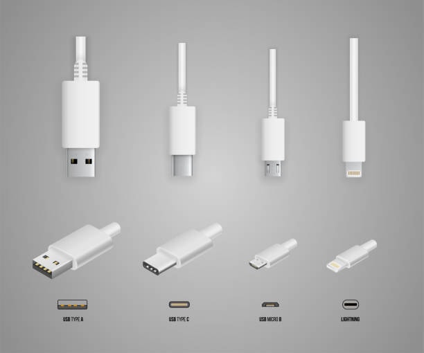
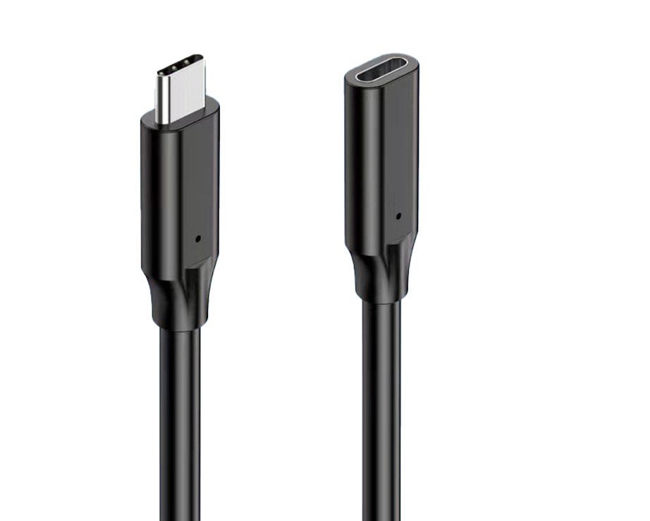
USB Type-C Cable Wiring
New USB Type-C has become the most versatile interface since it allows users to insert the connector either way and provides better power distribution with high-speed data transfer capabilities. A complete USB Type-C connector houses 24 pins that multiply into multiple wires across the cable structure. A combination of comprehensive features is possible with USB 3.1 cables that are also compatible with both USB 3.0 and USB 2.0 systems.
A USB Type-C cable includes the following wires:
- VCC (Power) – Red Wire
- Data+ (D+) – Green Wire
- Data- (D-) – White Wire
- Ground (GND) – Black Wire
- SuperSpeed Data+ (SS Data+) – Blue Wire
- SuperSpeed Data- (SS Data-) – Yellow Wire
- Shielding Wire functions as Ground Shield (GND).
- Technology that supports Power Delivery (PD) involves supplementary wires.
Additional advanced power delivery protocols operate through these wires which accelerate fast device charging between laptops, smartphones and tablets.
USB OTG Cables: Wiring for On-The-Go Devices
Usage of USB On-The-Go cables lets mobile devices connect smartphones with USB peripherals that include flash drives and keyboards and mice. A USB OTG cable features an exclusive physical design since it enables mobile devices to function simultaneously as a peripheral and host device mini and micro connectors.
A USB OTG cable typically has the following wires:
- VCC (Power) – Red Wire
- Data+ (D+) – Green Wire
- Data- (D-) – White Wire
- Ground (GND) – Black Wire
Each end of OTG cables behaves differently because one connector features either micro-USB or USB-C while the other connector operates with traditional USB-A.
Slutsats
The internal wiring of USB cables proves complex and differs among USB standards even though they often appear basic to users at first sight. The number of wires within USB cables increases as the function requirements grow from four wires in USB 2.0 to twenty-four wires in USB Type-C cables. Each various USB interface standard including USB 3.0, USB 3.1, USB Type-C and USB OTG features a specific wiring pattern that enables fast data transfer speeds and higher power delivery along with extra functionality.
Modern digital connectivity operates through USB cables which engineers design intricately despite their low-profile position in the technology field.The interlocking components within USB cables perform essential device applications and data transfer because of their intricate engineering plan.nectivity. From charging our devices transferring critical data, these cables perform vital functions thanks to the carefully engineered interplay of their components. The study of USB cable construction alongside electrical wiring both enhances our perception of their design while granting us the necessary knowledge to fix and modify these cables for specialized usage needs.A USB cable functions through its internal wires that combine to deliver both power and data signals. Standard USB 2.0 cables have four primary wires for power delivery and data transmission yet modern USB 3.0 and USB Type-C standards need additional wires to support increased speeds, enhanced power delivery capability and broader operational flexibility. Several protective components integrate within cables to safeguard wires against damage and outside disturbances which allows these cables to maintain high operational reliability under harsh conditions.
Successful USB cable wiring and repair projects require access to both essential tools and required materials. Each component starting with wires strippers up to the soldering iron implements vital functions to produce both accurate work and successful results. An added layer of protection is achieved by using both heat shrink tubing and electrical tape to cover connections which enhances safety while increasing cable toughness. The multimeter enables complete testing to confirm accurate wiring design without any detected. One major advancement of USB cables comes from USB-C technology with its reversible connector design which delivers stronger power and higher speed data transfer capability. The USB industry continues to advance because innovative designs prove that technology needs of modern electronics are still growing. Despite these advancements, the foundational principles of USB wiring remain constant: an emphasis on efficiency, reliability, and adaptability.
Summary
USB cables throughout various categories do not follow one standardized wire count. Standard USB 2.0 cables use four wires yet USB 3.0 cables incorporate nine wires alongside the same maximum cable length of 24 pins that USB Type-C cables can contain. Cables transport power and data through wires which support current devices including smartphones and laptops. Users create better cable choices for their devices through understanding of internal cable wiring. A USB cable delivers reliable power transfer and data transmission because each element including core wires and outer insulation stands as the result of careful design. A complicated design exists beneath everyday use of USB cables which plays an essential role in their operational durability.


